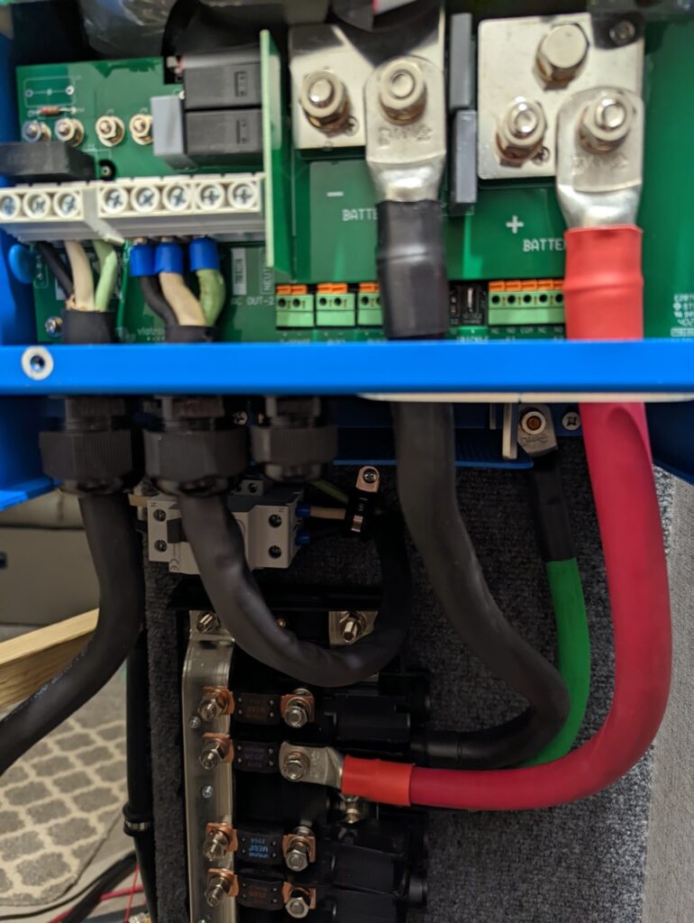
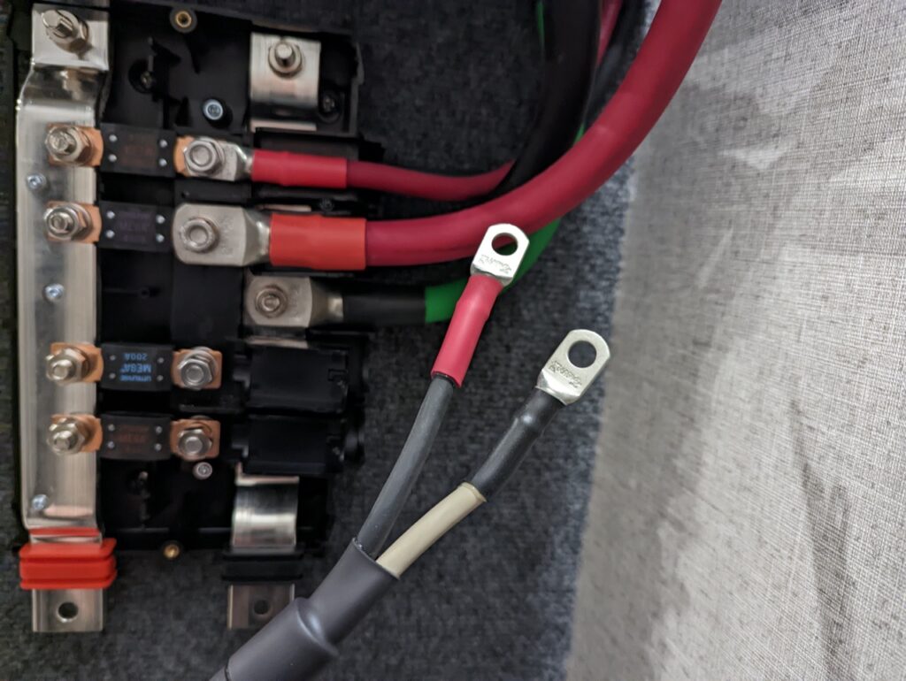
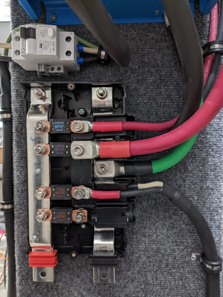
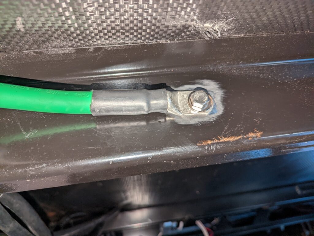
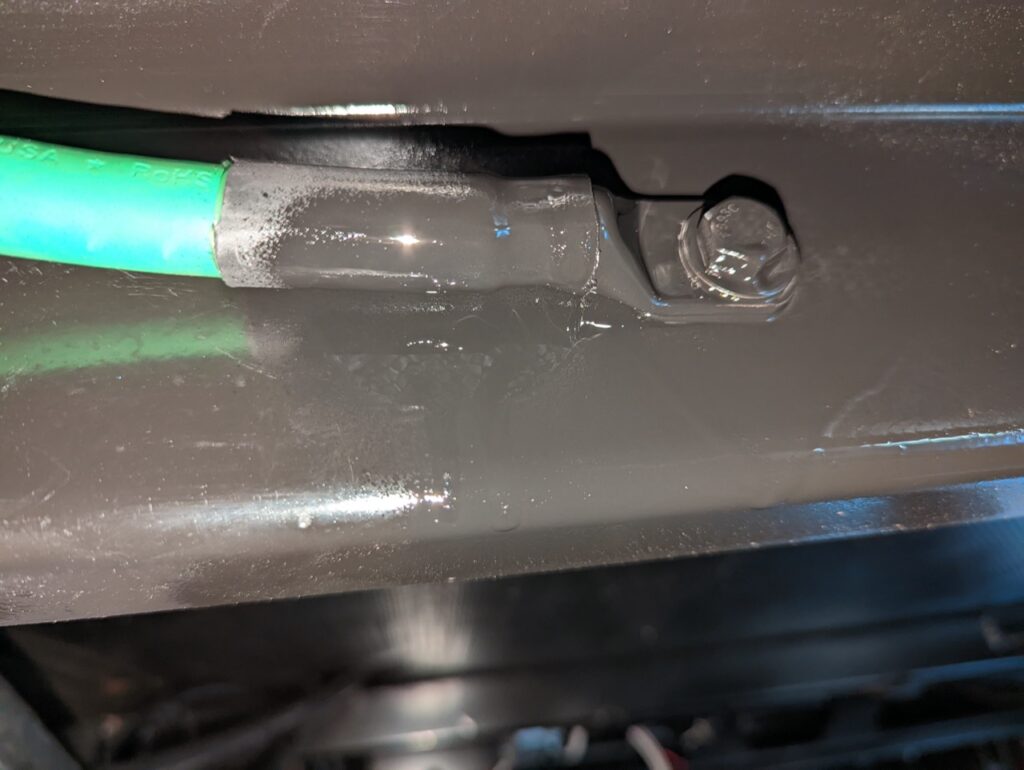
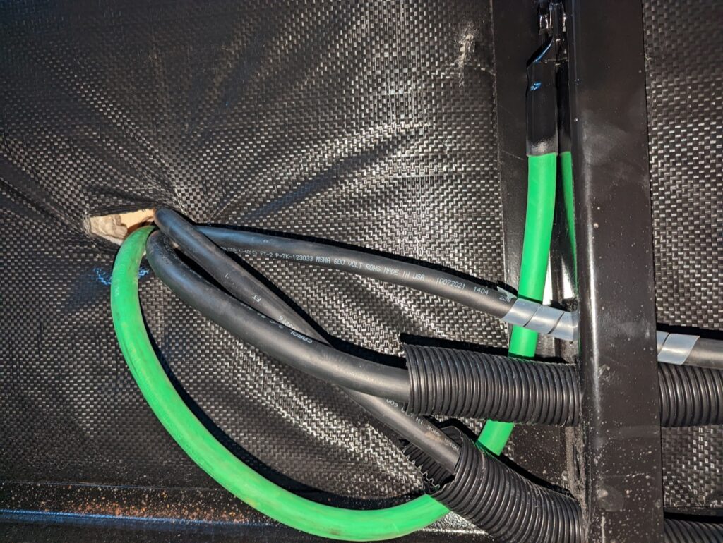
In the first post on this topic I covered the physical install and mounting of the major components. This post will focus on the wiring of the components. Wiring is a big part of the build. Check out this post about the wiring, connectors, etc I used (ADD LINK).
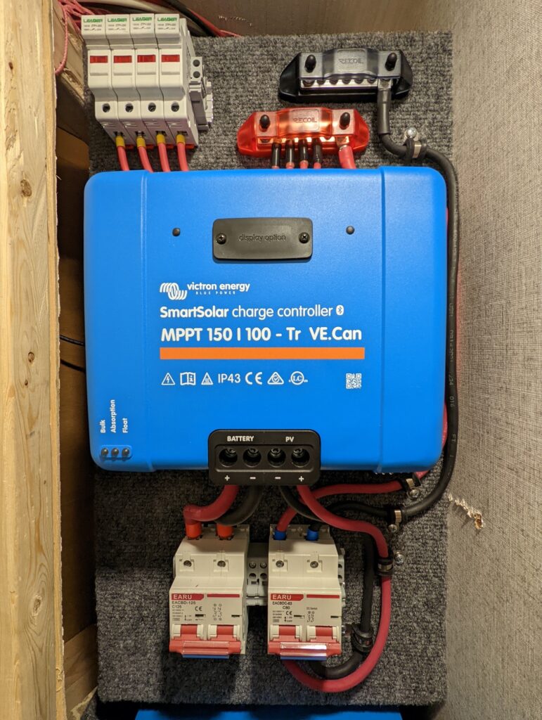
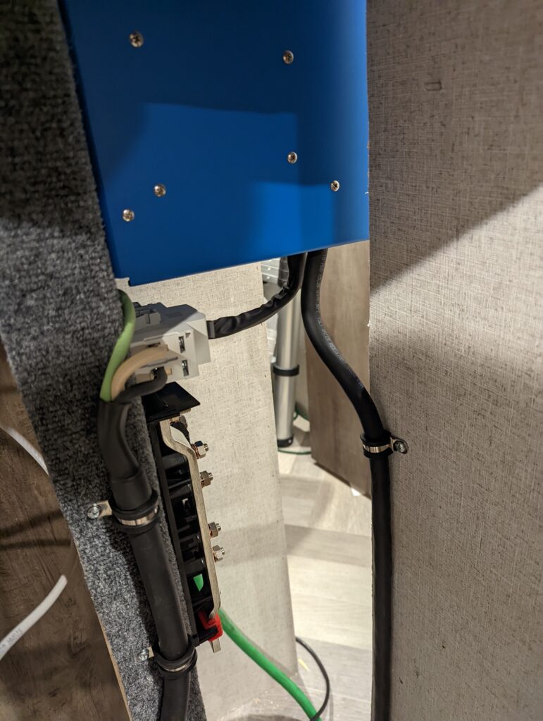
The solar panels use a PV/Use-2 10awg stranded copper wire that runs down into the camper. Each of the four panels positive cable runs through a 20 amp solar fuse that also works as disconnect. The same 10awg PV wire then runs from the fuses to the positive bus bar. The negative cables go to a negative bus bar. Two 6awg wires (flexible welding cable) run from the bus bars to a 80 amp DC breaker, then to the PV input of the solar charge controller. From the battery output of the solar charge controller 2awg wire is used and runs through a 125 amp DC breaker. It will eventually terminate in the Lynx bus bar beneath the inverter. The DC breakers allow for the isolation of the solar charge controller. It is important to always turn on the battery breaker before the PV breaker (and PV first when turning off).
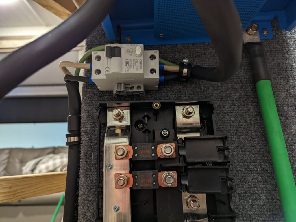
The use of a RCD/GFCI on the output of the inverter seems to be a foggy topic. I decided to try to include the protection on my install and will update it if becomes an issue. The RCD I sourced is 30mA vs the more common 5mA that a traditional outlet based GFCI is. 30mA is the max rating that still provides protection for people and will work with appliance that might trip a 5mA GFCI.
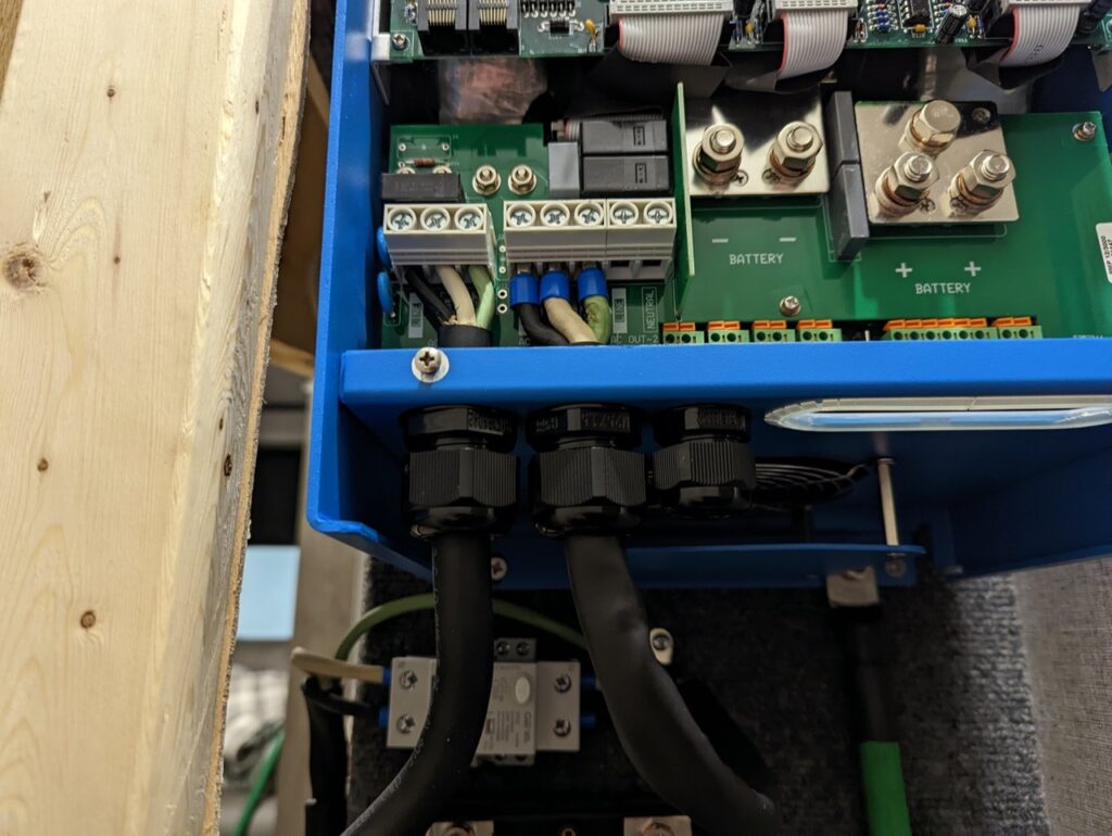
A tip when hooking up the inverter. 6/3 SOOW cord will not fit in the output cable gland. Strip the outer insulation off the SOOW cord and use heat shrink to keep a clean look and have something that will fit through the cable gland. The next struggle is installing the 6awg in the terminal blocks on the multiplus. You will not be able to get the bare stranded wire in there. The crimped wire ferrules made all the difference.
