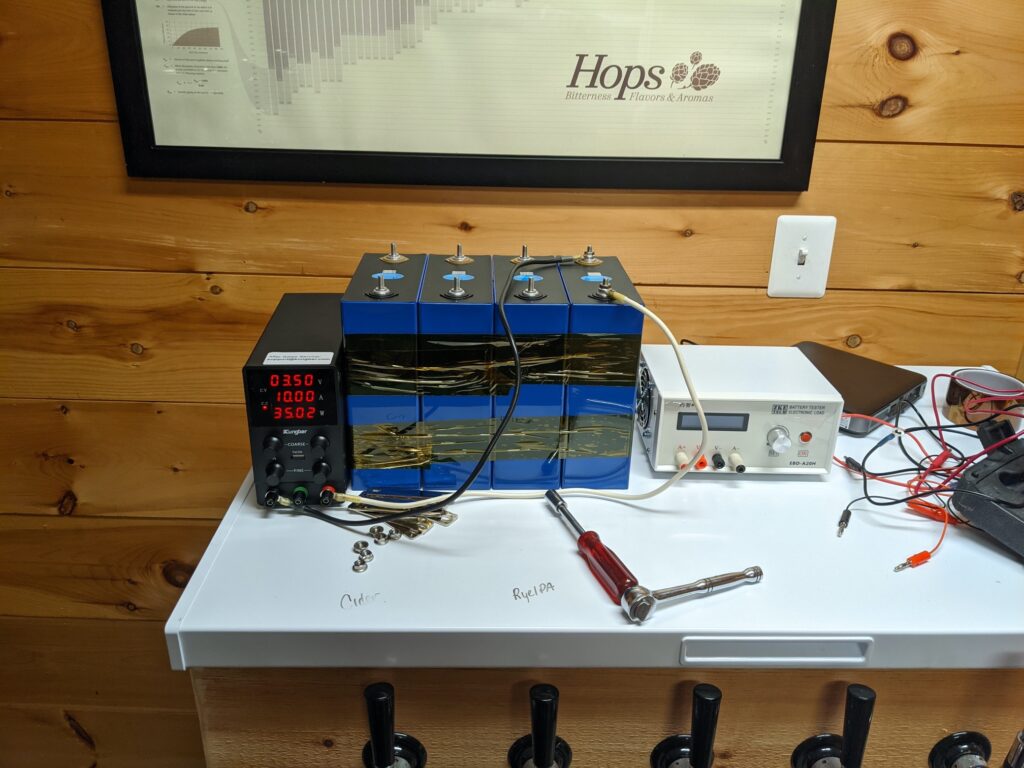
I chose to DIY a lithium iron phosphate (LFP) battery bank. This involves sourcing LFP cells and a battery management system. I will be building a 12v 608ah battery bank made up of two 12v 304ah batteries connected in parallel. Each battery will contain four 3.2v 304ah prismatic LFP cells and a 150 amp 4s Smart BMS by JBD. This will give me a max sustained discharge and charge of 300 amps. I would have preferred a little higher of a charge and discharge rating on the BMS’s for some buffer but stepping up would be a lot more money. I will see how the current system work before making any changes. JBD has since come out with a 200a 4s Smart BMS option (August 2021).
The inverter is the highest draw device at 3000va / 2400w. The Multiplus is a low frequency inverter so rough math would state I need 2400w * 1.5 low frequency factor / 12v low voltage cut off = 300 amps.
Cell Sourcing
It took about three months from order date for the LFP cells to arrive from my supplier in China. I worked with Amy Wan at Shenzhen Luyuan Technology Co., Ltd. She had a good reputation on the diy solar forum. It is important to find good supplier. You are likly to have a disappointing experience if you order from just any listing on Alibaba or Aliexpress. Amy was not the cheapest option but the cells are grade A, matched, and well packaged which is worth paying for. Many listings will say they are for grade A matched cells but that is not what you will receive.
Cell Testing
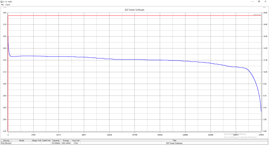
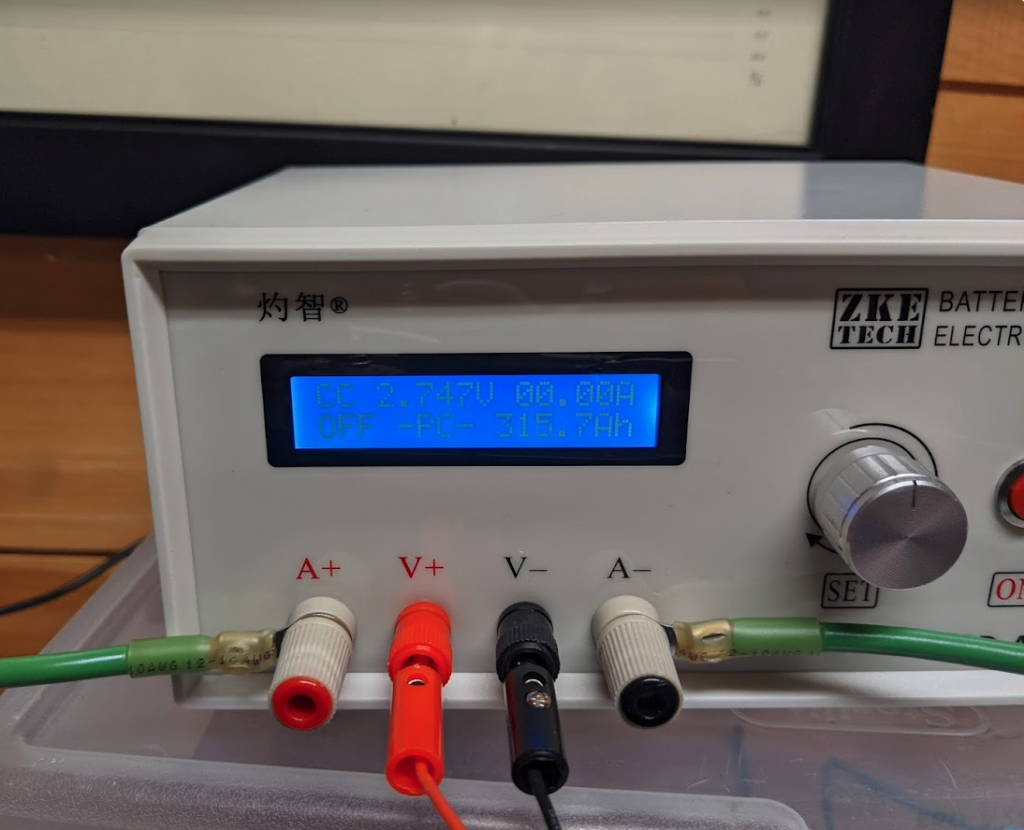
After receiving the cells the first step is to validate the capacity and resistance of each. I am using a ZKE EBD-A20H battery tester. The goal will be to run the batteries between 10% and 90% state of charge. The charge and discharge charts will help inform where I should run my cut off voltages and how many amp hours to expect in the working range. If the cells test at ~320ah per the factory data that should be about 250ah of usable capacity each for a total of 500ah.
The factory data for each cell was shared by the supplier after they shipped. The code for each cell is broken down as follows.
Example: 04QCB73712200JB6M0002686
- 04Q – Vendor code for Eve Power
- C – Production type – Cell
- B – Cell type – LiFePO4
- 73 – Model code – LF304
- 712200 – Factory trace code
- 71 – Production line
- 22 – Task order
- J – Factory Address – Jingmen
- B6M – Date code in Hex
- B – 2021
- 6 – June (1-9, then A-C)
- M – 22nd (1-9 then A-V)
- 0002686 – The 2,686th piece made that day
| No | Code | Capacity(Ah) | OCV1(V) | Ri1(mohm) | OCV2(V) | Ri2(mohm) | OCV3(V) | Ri3(mohm) |
| 1 | 04QCB73712200JB6M0002686 | 321.4197 | 2.795 | 0.16 | 2.783 | 0.16 | 3.298 | 0.15 |
| 2 | 04QCB73712300JB6M0000124 | 321.4957 | 2.792 | 0.15 | 2.779 | 0.15 | 3.298 | 0.15 |
| 3 | 04QCB73712300JB6M0000002 | 320.8327 | 2.793 | 0.16 | 2.778 | 0.16 | 3.298 | 0.15 |
| 4 | 04QCB73712300JB6M0000054 | 320.8498 | 2.79 | 0.16 | 2.775 | 0.16 | 3.298 | 0.15 |
| 5 | 04QCB73712300JB6M0000001 | 321.0312 | 2.79 | 0.16 | 2.775 | 0.16 | 3.298 | 0.15 |
| 6 | 04QCB73712300JB6M0000072 | 321.2002 | 2.79 | 0.16 | 2.775 | 0.16 | 3.298 | 0.15 |
| 7 | 04QCB73712300JB6M0000155 | 321.4745 | 2.794 | 0.16 | 2.78 | 0.16 | 3.298 | 0.15 |
| 8 | 04QCB73712300JB6M0000174 | 321.6349 | 2.793 | 0.16 | 2.778 | 0.16 | 3.298 | 0.15 |
Cell Test Results
Each cell will be charged with a 30v 10a CV/CA bench top power supply. I will then use the load tester to record the discharge curve and capacity. Once done I will set the cells to 50% charge and wait until I am ready to top balance and build them into 4s 12v battery packs.
I quickly found that the bench top power supply would not supply 10 amps @ 3.6v with the wires that are included with it. I tried adding ring terminals to the included wires but it was not enough. The wire is not marked but is likely 16-14awg. I replaced it with 10awg copper fine stranded wire with ring connectors on both ends. This allowed the power supply to run at its full 10 amps.
Even if the cells are shipped with 50% charge each cell will take over 15hrs (304*.5/10) to fully charge. It will take a similar time frame to discharge (304/20) with my 20 amp load tester. You can speed up the process by building a 12v pack (with BMS) and charging it most of the way with a high power charger like the Multiplus. You can then top off the individual cells in much less time then test. I would go with a combo charger/load tester that can automate this process if I was doing this again or had more cells. ZKE make a EBC-A40L that will charge and discharge up to 40 amps but only at 5v or less. The ZKE EBD-A20H I am using will discharge only at up to 30v and 20amps. I have the EBD-A20H hooked up to a old Intel Atom PC via USB to use the logging software it includes.
I tested two cells by charging to 3.6v and down to 2.6v. I could have run from 3.65 to 2.5v if I wanted to. Both tests achieved over 315ah. Which exceeds the 304ah rating and matches my expectation for the quality of cell I received. Since I am using Smart BMS’s with bluetooth I will be able to monitor individual cell voltages in the battery. Rather then take the time to test every cell I am going to top balance then build my 12v packs and do another charge/discharge test. Both the charger and discharger I am using can operate at 12v so I can test the whole battery just as fast as a single 3.2v cell.